
C10: Inside Computers
What we didn't realize then was that the integrated circuit would reduce the cost of electronic functions by a factor of a million to one; nothing had ever done that for anything before. — Jack Kilby
People usually compare the computer to the head of the human being. I would say that hardware is the bone of the head, the skull. The semiconductor is the brain within the head. The software is the wisdom. And data is the knowledge. — Masayoshi Son
Recall from Chapter C4 that early computing devices, such as Pascal's calculator (1642) and Babbage's Analytical Engine (1833), were purely mechanical. Such devices stored information as different settings on dials and cogs and then processed this information in response to physical actions (e.g., turning a crank to spin interlocking wheels). Modern computers, by contrast, are powered by electricity, using electrical signals to store and manipulate information. This chapter begins by reviewing the fundamental properties of electricity, as well as the importance of electrical switches (e.g., relays, vacuum tubes or transistors) to computing technology. After covering these basics, the chapter describes transistors, the building blocks of modern computers, and the ways in which transistors can be combined into circuits that store values and perform operations. We end the chapter with a discussion of integrated circuits, microprocessors, and the manufacturing techniques used to create computer chips.
Electricity and Switches
Computers, along with most modern machines, are electrical devices. The components of a computer require electrical power to carry out their assigned tasks. For example, electricity generates the light that shines through a computer screen, illuminating the individual pixels that make up images and letters. Electricity also runs the motor that spins the hard drive, allowing information to be accessed. In addition, the main memory and CPU employ electrical signals to store and manipulate data. Although we are all familiar with electricity in that we use it every day, understanding the details of electrical currents and their properties requires significant knowledge of physics.
Simply stated, electricity is a flow of electrons — the negatively charged particles in atoms — through a medium. Elements such as copper, silver, and gold are especially good at conducting electricity, meaning that their molecular structure can accommodate the flow of electrons with little resistance. To ensure the efficient delivery of electricity, most power lines are constructed from copper wire, whereas computers often use copper, silver, palladium and/or gold for connecting electrical components. Other elements, especially nonmetals such as carbon and oxygen, are poor conductors of electricity.
Electricity can be quantified in various ways. An ampere, or amp, is a unit that gauges electron flow: 1 amp of current is equal to 6.24 quintillion (6.24 × 10¹⁸) electrons flowing past a given point each second. Another common measure of electricity is voltage, which corresponds to the physical force produced by the flow of electrons. In the United States, standard household outlets carry 110 or 120 volts; in Europe, 220-volt outlets are more typical.
The most basic tool for controlling the flow of electricity is a switch. A switch is a device designed to connect or disconnect two wires, thus regulating the flow of electricity between them. For example, a light switch on a wall serves as an intermediary between the power line entering your home and the outlet that operates a lighting fixture. If the switch is in the "on" position, then the wires that link the outlet to the power line are connected and the lighting fixture receives electricity (FIGURE 1, top). However, if the switch is turned off, then the connection is interrupted, and no power reaches the outlet (FIGURE 1, bottom). In this and subsequent figures, a thick green line symbolizes a wire carrying electrical current, whereas a thin black line symbolizes a wire carrying no current.
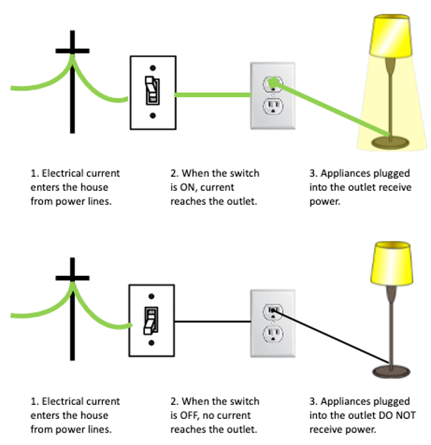
FIGURE 1. A light switch controls the flow of electricity from outside power lines to household appliances.
✔ QUICK-CHECK 10.1: TRUE or FALSE? Electricity is the flow of electrons through a medium.
✔ QUICK-CHECK 10.2: In addition to a light switch, identify another common device that utilizes an electrical switch.
Transistors
Computers store and manipulate information as electrical signals. Because switches are integral to controlling electrical flow, it should not be surprising that computer components such as main memory and the CPU incorporate switches. In fact, advances in switching mechanisms have defined the different generations of computer technology (see Chapter C4). The first electronic computers (Generation 0) were built in the 1930s using switches called electromagnetic relays. These relays were mechanical switches whose on/off positions were controlled by voltage to a magnet. In the 1940s, the replacement of relays with vacuum tubes launched the next generation of computers (Generation 1). Although vacuum tubes could be turned on and off as if they were mechanical switches, the tubes' lack of moving parts enabled them to shift between states much more quickly than relays could. However, vacuum tubes had a downside — they generated large amounts of heat and tended to burn out frequently. In 1948, John Bardeen, Walter Brattain, and William Shockley at AT&T Bell Labs invented the transistor, ushering in yet another generation of computer technology (Generation 2).
A transistor, considered by many to be the most important invention of the 20th century, is a solid piece of metal attached to wires that serves as a switch by alternatively conducting or resisting electricity (FIGURE 2). Transistors are similar to vacuum tubes in that they contain no moving parts; however, transistors are smaller, more reliable, and more energy efficient than vacuum tubes. Because of these advantages, transistors enabled hardware experts to design smaller, faster machines at a drastically lower cost.
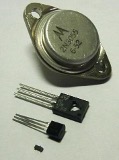
FIGURE 2. Early transistors (Transisto/Wikimedia Commons).
Although the first transistor was made of germanium, modern transistors are constructed from the much cheaper silicon. Both germanium and silicon belong to a category of elements called semiconductors, which are metals that can be manipulated to be either good or bad conductors of electricity. Through a process known as doping, impurities are added to a slab of a semiconductor, causing the metal to act as an electrical switch. Today, most transistors are built using metal oxide semiconductor (MOS) technology. A positively doped metal-oxide semiconductor (PMOS) transistor contains silicon doped with impurities that make it conduct electricity be default, but it can be made nonconductive by applying current to a separate control wire.
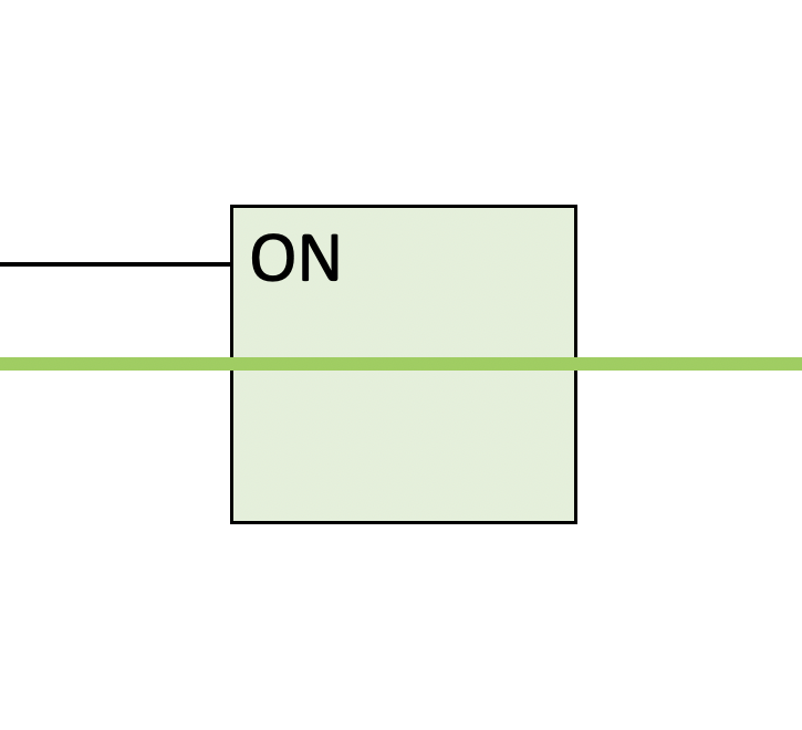
FIGURE 3 illustrates a PMOS transistor as a box with three wires, the control wire, the input wire and the output wire. As in FIGURE 1, wires with no electrical current (0V) are drawn with a thin black line whereas wires with current (5V) are drawn with a thick green line. The control wire determines the conductivity of the transistor, essentially opening and closing the switch. The diagram shows the transistor in its default state (with 0V on the control wire). which is conductive (labeled ON). The current entering on the input wire is able to flow through the transistor and out the output wire. If you select 5V on the control wire, this will flip the transistor to its nonconductive state (labeled OFF). The current entering along the input wire is blocked and thus no current reaches the output wire.
| control
input |
 |
output |
FIGURE 3. Interactive PMOS transistor.
✔ QUICK-CHECK 10.3: Confirm the behavior of the PMOS transistor by selecting 5V for the control wire (i.e., click on the box with 0V and slide down to select 5V). Does this change the control wire to green (designating electrical current) and change the state of the transistor so that no electricity flows to the output wire, as described?
Although transistors were initially more expensive than their vacuum tube counterparts, the benefits that transistors offered in terms of size, power consumption, heat dispersal, and longevity far outweighed the cost disadvantage. The year 1953 marked the launch of the first transistor-powered commercial product, a hearing aid, which was followed by the transistor radio in 1954. A year later, researchers at Bell Labs constructed the first computer built entirely with transistors. As mass production techniques improved throughout the 1950s, the cost of manufacturing transistors dropped steadily, and transistors soon replaced vacuum tubes in virtually all electronic appliances. In addition to commercial success, the invention of the transistor brought scientific recognition to Shockley, Brattain, and Bardeen, earning them the 1956 Nobel Prize in Physics (FIGURE 4).
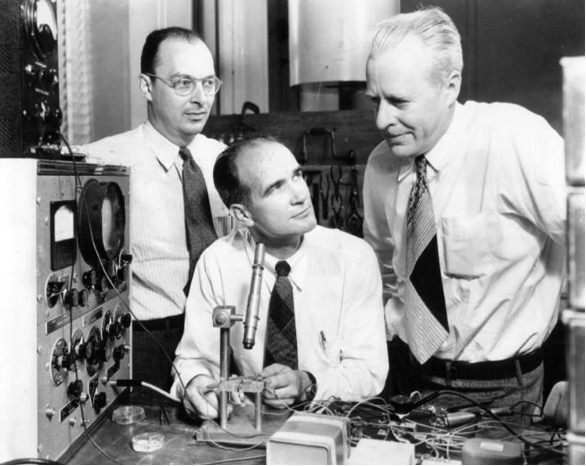
FIGURE 4. John Bardeen, William Shockley and Walter Brattain viewing an early transistor through a microscope (AT&T/Wikimedia Commons).
✔ QUICK-CHECK 10.4: TRUE or FALSE? Nonmetals such as carbon and oxygen tend to be good conductors of electricity.
✔ QUICK-CHECK 10.5: TRUE or FALSE? A semiconductor is a metal that can be manipulated to be either a good or a bad conductor of electricity.
From Transistors to Gates
At first glance, it is not obvious how a transistor — or any electrical switch, for that matter — can serve as the building block of modern computers. After all, computers are powerful machines that perform billions of complex mathematical and logical operations per second. How can a simple switch contribute to this impressive behavior? As this book has demonstrated, even the most intricate computer functionality is produced by combining sequences of simpler components. For example, Chapter C1 taught you that, although a single bit can differentiate between only two different values, a collection of 8 bits (a byte) can represent any character on a keyboard. Likewise, in Chapter X6, you saw that simple JavaScript statements can be joined to create functions that carry out complex computations. In much the same way, transistors can be combined to form complex circuits, which perform the underlying operations of computers.
A circuit is a collection of transistors (and possibly other electronic components) wired together to produce a particular behavior. The simplest useful circuit is a single PMOS transistor connected to a power supply (FIGURE 5). In this circuit, the roles of the control and input wires are reversed, with the input to the circuit connecting to the control wire of the transistor and the power supply connected to the transistor's input wire. The result is a circuit whose output is the opposite of its input. For example, the diagram in FIGURE 5 shows an input of 0V and an output of 5V (since the control wire to the transistor has no current, the transistor is ON and the current from the power source flows through). If you select 5V on the input wire, the output wire flips to 0V (since current on the control wire turns the transistor OFF and current from the power source is blocked). This simple circuit is known as a NOT gate.
| input | 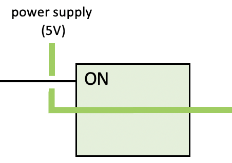
|
FIGURE 5. Interactive NOT gate.
✔ QUICK-CHECK 10.6: Confirm the behavior of the NOT gate by selecting 5V for the control wire. Does this change the control wire to green and change its state so the output wire has no current?
Gates and Binary Logic
The term gate refers to the fact that this simple circuit controls the flow of electricity in much the same way that a wooden gate controls traffic flow through a fence. In the case of a NOT gate, the flow of electricity is manipulated so that the output signal is always the opposite of the input signal (input voltage → no output voltage; no input voltage → output voltage). Although it is accurate to describe a gate's inputs and output as voltage levels, we can think of these inputs and outputs more abstractly in terms of binary values: 0 representing no current and 1 representing current. From this perspective, we can think of a gate as computing a function on binary values. The table on the righthand side of FIGURE 6 lists each possible input value for a NOT gate, along with its corresponding output value. The left-hand side of the figure depicts a symbol that is often used to represent a NOT gate; this notation abstracts away all the circuit's underlying details, allowing a designer to draw the circuit simply and easily.
|
|

FIGURE 6. Symbol and behavior of a NOT gate, with 1 denoting current and 0 denoting no current.
You may have noticed a similarity between the NOT gate and the JavaScript logical connective ! from Chapter X7. In fact, the NOT gate inverts voltages in the same way that the ! operator inverts Boolean values (!true → false; !false → true). If we replaced 0 with false and 1 with true, the table from FIGURE 6 would perfectly describe the behavior of the ! operator. For this reason, tables that describe the mapping from circuitry inputs to outputs are known as truth tables.
In addition to the NOT gate, other simple circuits can be defined to perform useful tasks. FIGURE 7 shows how two transistors can be wired together to form an AND gate, which corresponds to the JavaScript connective &&. Note that the output wire carries current only if both the input1 AND input2 wires carry current. FIGURE 8 shows the abstract symbol used to represent an AND gate, along with its truth table.
| input1
input2 | 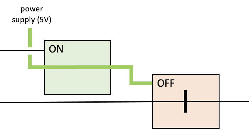
| output |
FIGURE 7. Interactive AND gate.
|
|

FIGURE 8. Symbol and behavior of an AND gate, with 1 denoting current and 0 denoting no current.
✔ QUICK-CHECK 10.7: Confirm the behavior of the AND gate by selecting different input values in both FIGURE 7 and FIGURE 8. As the truth table shows, the output of an AND gate should produce current only if both input wires carry current.
Similarly, FIGURE 9 depicts the circuitry and behavior of an OR gate, which corresponds to the JavaScript connective ||. The output wire of an OR gate carries current as long as either the input1 OR input2 wire carries current. FIGURE 10 shows the abstract symbol used to represent an OR gate, along with its truth table.
| input1
input2 | 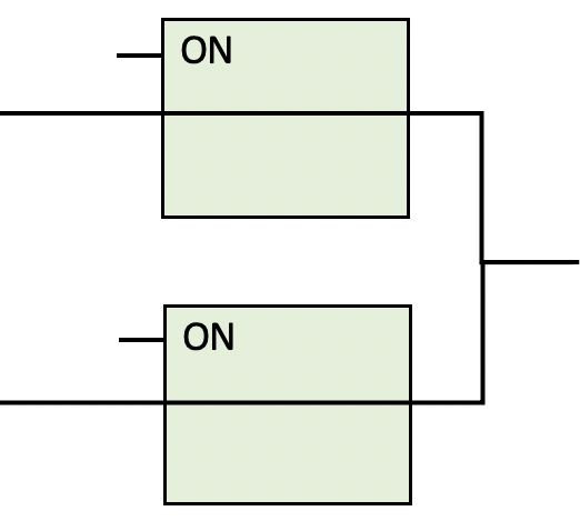
| output |
FIGURE 9. Interactive OR gate.
|
|

FIGURE 10. Symbol and behavior of an OR gate, with 1 denoting current and 0 denoting no current.
AND, OR, and NOT gates are the simplest circuits that perform well-defined logical operations. By combining these primitive circuits, a hardware designer can construct all the logic required to store and manipulate information within a computer.
✔ QUICK-CHECK 10.8: Confirm the behavior of the OR gate by selecting different input values in both FIGURE 9 and FIGURE 10. As the truth table shows, the output of an OR gate should produce current if one or both input wires carry current.
From Gates to Complex Circuits
Just as simple transistors can be wired together to form gates, individual gates can be wired together to form complex circuitry that performs specific tasks. To demonstrate the process of designing logical circuitry, consider the task of adding two numbers, which is one of the basic tasks carried out by a CPU. For simplicity, we will limit ourselves to the task of adding 4-bit numbers. For example, 01012 + 11002 = 100012.
Before we continue, it might help to quickly review the rules of binary addition. In principle, adding binary (base 2) numbers is no different from adding decimal (base 10) numbers. Recall that, in decimal, corresponding columns of digits are added together, starting from the right. If the sum of any two digits yields a 2-digit number (a number > 9), then the 1 is carried over to the next column. Similarly, in binary, corresponding bits are added together, starting from the right. If the sum of any two bits yields a 2-bit number (a number > 1), then the 1 is carried over to the next column.
For example, FIGURE 11 portrays two different examples of binary addition. In the example on the left, adding the rightmost bits 1 and 1 produces a sum of 102 (decimal value two). Thus, a 0 is written in the rightmost column of the result and a 1 is carried over to the next column. The sum of the second set of bits then becomes 102 because of the previous carry, causing a second 0 to be written in the result and a 1 to be carried over to the third addition. In the example on the right, a 1 is carried over after adding the leftmost bits. In such an instance, the sum of the numbers will contain one more bit than the input values (in the same way that 9 + 9 = 18).
FIGURE 11. Examples of binary addition.
✔ QUICK-CHECK 10.9: What is the sum of 1012 and 12?
✔ QUICK-CHECK 10.10: What is the sum of 1102 and 112?
Although binary addition is a relatively straightforward operation, designing a circuit for adding binary numbers is far from trivial. If we attempted to design such a circuit from scratch using transistors, the complexity involved would be overwhelming. However, if we think of circuit design in terms of multitiered complexity, then the underlying layers can establish abstractions that simplify the upper layers. For example, instead of starting at the transistor level, we can use logical gates AND, OR, and NOT as building blocks to create a simple circuit for adding 2 bits. Such a circuit contains two input lines, representing the bits to be added, and two outputs, representing the sum of the inputs and a possible carry. This functionality can be implemented using only four gates, as illustrated in FIGURE 12. In the pictured configuration, the first input has a value of 1 and the second input has a value of 0, yielding a sum of 1 and a carry of 0. However, if you changed both inputs to 1, the result would be a sum of 0 and a carry of 1. This circuit is known as a half-adder.
|
| 
| carry
sum |
FIGURE 12. Interactive half-adder.
The term "half-adder" refers to the fact that, when you add binary numbers containing more than one bit, summing the corresponding bit pairs by column is only half the job. As you add up each column, you must also consider that a bit might be carried over from the previous addition. Thus, adding corresponding bits in two numbers requires the ability to add 3 bits: the two input values and a possible carry. Using half-adders and logical gates as building blocks, we can design a circuit that performs this task. FIGURE 13 depicts such a circuit, which is known as a full-adder and consists of two half-adders and an OR gate. In the pictured configuration, two of the inputs have values of 1, yielding a sum of 0 and a carry of 1. If you changed all three inputs to 1, it would yield a sum of 1 and a carry of 1.
|
| 
| carry
sum |
FIGURE 13. Interactive full-adder.
Finally, using full-adders as building blocks, we can design a more complex circuit that sums two 4-bit numbers. Because a full adder is required to add each corresponding bit pair together (along with a possible carry from the previous addition), the appropriate circuit will encompass four full adders wired together (FIGURE 14). In the pictured configuration, the two input numbers are 01012 and 00112, yielding a sum of 010012.
|
| 
|
FIGURE 14. Interactive circuit for adding 4-bit numbers.
It is not difficult to expand this design to be able to add longer bit sequences. For example, to add 8-bit numbers, you would wire eight full-adders together in a similar cascading pattern.
✔ QUICK-CHECK 10.11: Confirm the behavior of the circuits in FIGURES 12-14. In particular, use the interactive circuit from FIGURE 14 to confirm your answers from QUICK-CHECKS 10.9 and 10.10.
Designing Memory Circuitry
In addition to performing calculations such as adding numbers, electronic circuitry is also used to implement memory that the CPU can access quickly. For example, both RAM and cache are composed of circuitry. However, the circuitry used to store bits in memory is different from the circuitry that performs operations such as addition. Whereas adders manipulate inputs to produce outputs, memory circuits must maintain values over time. The simplest circuit for storing a value is known as a flip-flop. A flip-flop stores a bit whose value can be set to 1 by applying current to one input wire (known as the Set wire) and then reset to 0 by applying current to another input wire (known as the Reset wire). In effect, the Set wire flips the memory bit on, while the Reset wire flops it off.
It is important to note that a flip-flop maintains the last value assigned to it, either a 1 if current was most recently applied to the Set wire or a 0 if current was most recently applied to the Reset wire. Thus, setting or resetting a flip-flop requires only a brief current on the appropriate input wire. Once set or reset, the output of the circuit is constant. This behavior is achieved within the circuitry via a feedback loop, which causes the output of the circuit to circle back and refresh the inputs. The diagram in FIGURE 15 portrays a flip-flop that is constructed from two AND gates and four NOT gates. Note that the outputs of the rightmost NOT gates loop back and serve as inputs for the AND gates. As shown, this flip-flop can be thought of as storing a 0, since the output wire has no current on it. If you click on the "Set bit" button, however, a burst of current travels on the Set wire and flips the state of the circuitry, producing a steady current on the output wire. If you subsequently click on the "Reset bit" button, a burst of current on the Reset wire resets the circuitry and no current flows from the output wire.
|
FIGURE 15. Interactive flip-flop.
In much the same way that full-adders can be wired together to produce the ALU's complex circuitry, flip-flops can be wired together to construct the registers and main-memory cells of a computer.
✔ QUICK-CHECK 10.12: Confirm the beahvior of the flip-flop in FIGURE 15. When you click on the "Set bit" button, does the electricity in the circuit change, resulting in a 1 being stored? Likewise, does clicking the "Reset bit" button result in 0 being stored?
From Circuits to Microchips
Initially, circuits were built by wiring together individual transistors. If a hardware designer wished to create a new computer component, they would assemble a large number of transistors and physically connect them using wire and a soldering iron. In addition to being extremely tedious and error prone, this approach did not lend itself to mass production. Every time a particular circuit was needed, it had to be constructed from scratch out of transistors and wire. Furthermore, there were limitations to the minimum size of circuits built from individual transistors. As the spacing of transistors within circuits had to accommodate human hands that inserted and soldered the wires, even simple circuits consisting of tens or hundreds of transistors were quite large.
The Integrated Circuit
In 1958, two researchers independently developed techniques for manufacturing mass-produced, smaller circuitry: Jack Kilby (1923-2005) at Texas Instruments and Robert Noyce (1927-1990) at Fairchild Semiconductor Corporation. They both realized that, to enable the mass production of circuits, all the components (including transistors and their connections) would have to be constructed as a single unit. Each researcher proposed a manufacturing process in which circuitry is layered onto a single wafer of silicon, known as a microchip. Because every component of the circuit was integrated onto the same microchip, these circuits became known as integrated circuits.
In 1959, both Texas Instruments and Fairchild Semiconductor applied for and were awarded patents on their microchip-manufacturing techniques. After several years of legal battles, the two companies agreed to cross-license their technologies, which marked the beginning of the computer microchip industry. After leaving Fairchild Semiconductor, Noyce went on to cofound Intel, today's dominant microchip producer. Kilby was awarded the 2000 Nobel Prize in Physics in recognition of his contribution to the development of the integrated circuit.
The production of integrated circuits is perhaps the most complex engineering process in the world. The transistors that are manufactured on a microchip can be as small as 3 nanometers (3 × 10⁻⁶ meters), or roughly 1/33,000th the width of a human hair. To achieve precision on such a small scale, integrated circuit manufacturing relies heavily on techniques normally associated with film photography. Initially, the silicon chip is covered with a semiconductor material, then coated with a layer of photoresist — a chemical sensitive to ultraviolet light. The pattern of transistors to be layered onto the chip is printed on a mask, a transparent surface on which an opaque coating has been applied. Ultraviolet light is filtered through the mask, passing through the transparent portions and striking the surface of the chip in the specified pattern. The photoresist exposed to ultraviolet light reacts, hardening the layer of semiconductor below it. Once exposure is completed, the photoresist not exposed and the soft layer of semiconductor below are etched away, leaving only the desired pattern of semiconductor material on the surface of the chip (FIGURE 16). This process may be repeated up to 60 times, depositing layer upon layer of semiconductor material to form the circuit's transistors and their connections. Even the "wires" that connect the transistors are formed by depositing conductive material on the surface of the chip.
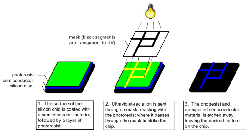
FIGURE 16. Adding a single layer of circuitry to a silicon chip.
Not surprisingly, manufacturing microchips requires extreme care and cleanliness. A single human hair or fleck of skin could damage thousands of transistors if it came in contact with the circuit. To prevent such problems, microchip production takes place in "clean rooms," where sealed ventilation systems remove airborne contaminants and workers wear protective suits that contain loose hair and skin cells.
✔ QUICK-CHECK 10.13: TRUE or FALSE? Jack Kilby and Robert Noyce are credited with independently inventing the integrated circuit.
✔ QUICK-CHECK 10.14: TRUE or FALSE? The main reason that workers wear protective clothing when manufacturing integrated circuits is to protect them from exposure to dangerous chemicals.
Packaging Microchips
Because the silicon chip containing an integrated circuit is fragile, it is encased in plastic for protection (FIGURE 17). Metal pins are then inserted on both sides of the packaging, facilitating easy connections to other microchips. It is safe to say that the microchip has revolutionized the way in which computers are designed and built. Useful circuits are implemented and mass produced as microchips. As microchips can be manufactured in bulk, their invention has drastically lowered the cost of constructing circuitry. Furthermore, the circuitry on microchips is extremely compact, which increases the speed of operations by shortening the distances over which electrical signals must travel. Today, the designers of computer systems do not even need to consider the low-level details of transistors and other electrical devices. Instead, they can simply select prebuilt microchips that contain the needed circuitry and wire those microchips together.
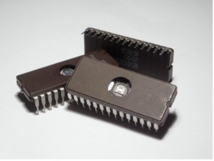
FIGURE 17. A microchip with circuitry visible in a cutaway portion of the case (Zephyris/Wikimedia Commons).
Improvements in manufacturing techniques and technologies are constantly reducing the scale of integrated circuits. In the early 1960s, a microchip one inch across might have contained the circuitry for five to ten logic gates. By the early 1970s, the space required to hold circuitry had shrunk to the point where a complete CPU could be manufactured on a single microchip, known as a microprocessor (or processor, for short). The first CPU contained entirely on a microchip was the Intel 4004. Released in 1971, the 4004 consisted of roughly 2,300 transistors and their connections. By the early 1980s, the era of Very Large Scale Integration (VLSI) was begun, where hundreds of thousands of transistors could fit on a single chip. By the 1990s, Ultra Large Scale Integration (ULSI) enabled millions and eventually billions of transistors per chip. Moore's Law, named after its originator Gordon Moore, describes this remarkable evolution of technology and manufacturing. Moore noted as early as 1965 that the number of transistors that could fit on a microchip doubled every 1 to 2 years. This observation (it is not, technically, a law) has been maintained for more than 40 years (FIGURE 18). As was discussed in Chapter C4, technology advances have slowed in the last decade, meaning that chip density no longer doubles as described by Moore's Law. However, the adoption of multicore processors has continued the overall effect described by Moore — the number of transistors in processors continues to double every 1 to 2 years, but at the cost of larger, multicore chips.
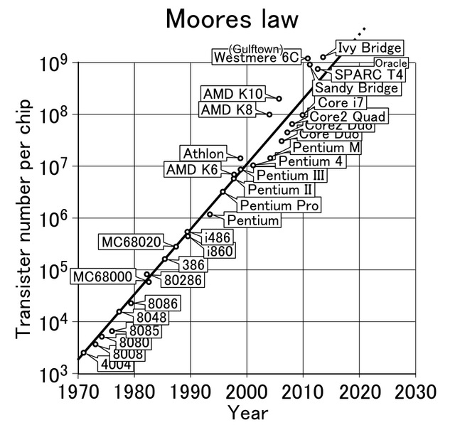
FIGURE 18. This graph (with a logarithmic scale) shows how processors have followed Moore's Law (shigeru23/Wikimedia Commons).
✔ QUICK-CHECK 10.15: TRUE or FALSE? Moore's Law dictates that integrated circuitry must be manufactured out of silicon, as opposed to other semiconductors such as germanium.
Chapter Summary
- Computers are electrical devices, requiring electricity to perform tasks such as illuminating the screen, powering the hard drive, and transferring data as electrical impulses.
- Electricity is a flow of electrons—the negatively charged particles in atoms—through a medium. Gold and copper are especially good at conducting electricity, and so they are often used to connect computer components.
- An electrical switch is a device designed to connect or disconnect two wires, thus regulating the flow of electricity between them. Switches can be implemented using a variety of technologies, including electromagnetic relays, vacuum tubes, and transistors.
- A transistor, considered by many to be the most important invention of the 20th century, is a solid piece of metal attached to a wire that serves as a switch by alternatively conducting or resisting electricity.
- Transistors are constructed from semiconductors—metals that can be doped with impurities to make them either good or bad conductors of electricity. The most common semiconductor used in modern transistors is silicon.
- A Positively doped Metal-Oxide Semiconductor (PMOS) transistor conducts electricity in its defaults state but does not conduct electricity when power is applied to its control wire.
- Because transistors were smaller, lasted longer, and required less power than vacuum tubes, they began replacing vacuum tubes in consumer devices in the 1950s (e.g., transistorized hearing aid in 1953, transistor radio in 1954, Bell Labs transistor computer in 1955).
- A circuit is a collection of transistors (and possibly other electronic devices) wired together to produce a particular behavior. The simplest circuits that perform well-defined logical operations are the NOT gate, AND gate, and OR gate.
- Tables that describe the mapping from circuitry inputs to outputs are known as truth tables.
- Simple circuits can be wired together to form more complex circuits. For example, starting with simple NOT, AND, and OR gates, the complex circuitry of the ALU can be designed and implemented.
- The simplest circuit for storing a value is known as a flip-flop. A flip-flop stores a bit whose value can be set to 1 by applying current to one input wire and then reset to 0 by applying current to another input wire.
- In 1958, Jack Kilby and Robert Noyce independently proposed manufacturing processes in which circuitry is layered onto a single wafer of silicon, known as a microchip. Because every component of the circuit was integrated onto the same microchip, these circuits became known as integrated circuits.
- To produce the incredibly small and precise circuitry on microchips (transistors can be 1/16,000th the width of a human hair), hardware manufacturers use light-sensitive chemicals to etch circuitry into layers of semiconductor materials.
- To protect the fragile silicon chip containing an integrated circuit, it is encased in plastic and packaged with metal pins to facilitate connections to other microchips.
- Moore's Law predicted that the number of transistors that can fit on a chip will double every 1 to 2 years.
Review Questions
- TRUE or FALSE? A circuit is a collection of transistors (and possibly other electronic devices) wired together to produce a particular behavior.
- TRUE or FALSE? If there is no electrical current on the input wire to a NOT gate, then there will be current on its output wire.
- TRUE or FALSE? The sum of the binary numbers 1012 and 12 is 1102.
- TRUE or FALSE? A flip-flop is a circuit that serves to store a single bit.
- Name three different technologies that, over the years, have served as electrical switches in computers. How were these technologies similar, and how were they different? What advantages or disadvantages did each provide?
- Electricians commonly wear rubber shoes and gloves to protect themselves when working with live wiring. Would this suggest that rubber is an efficient or inefficient conductor of electricity? Explain your answer.
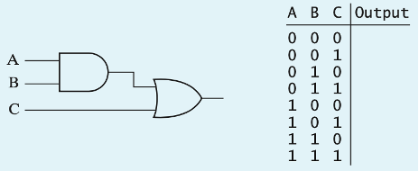
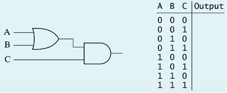
- It is possible to develop truth tables for logic circuits, just as we did for individual gates. For example, the logic circuit shown here combines an AND gate and an OR gate. Complete the corresponding truth table by calculating the output value for each set of inputs. [Hint: Figure out the output of the AND gate in each case and then use the result to determine the overall output.]
- The logic circuit shown here is similar to the one in the previous question, except that the AND and OR gates are in reversed positions. Complete the corresponding truth table by calculating the output value for each set of inputs.
- What is the sum of the binary numbers 1001012 and 10112? Show the steps you used to calculate your answer.
- What is the total number of gates required to build a 4-bit adder? Assuming one transistor per NOT gate (as in FIGURE 5) and two transistors per AND and OR gate (as in FIGURES 7 and 9, respectively), what is the total number of transistors in the circuitry of the 4-bit adder?
- Describe how a flip-flop can retain the last bit value assigned to it.
- In what way is integrated-circuit manufacturing similar to photography?
- Can Moore's Law continue to hold forever? That is, can technology continue to advance at the predicted rate indefinitely, roughly doubling the number of transistors every 1 to 2 years? Explain.